This website's SSL works best in Firefox.
In other browsers the Let's Encrypt SSL certificate may be
flagged as not-valid/expired and insecure but if the page
loads corrrectly after authorizing the exception then it will
still be encrypted. Ths website will not deliver content unencrypted !
Download the AM Stereo Tech Zone site in Zip.
If this site isn't regularly available in your area you may serve it out on the
net as needed.
NOTE: All GIF or BMP images on this site have been converted to PNG. If you get
a 404 Page (Not Found) from a search engine link try accessing the image with a
.png extension instead. You will probably find it. If you need access to the old
images they are zipped up here. Some TXT files have been
converted to PDF so try that also.
This page is for the promotion of
AM STEREO
for enthusiasts with technical info on tweaking your AM Stereo receiver plus
articles and graphs with the pros and cons of various systems.
Analog AM is still the best transmission mode for commercial broadcast bands
below 30MHz. Attempts at going to a digital system have not proven to be viable.
Receiver technology required is more complex and expensive. The power required
to run the digital processing is many times greater than a simple analog AM
radio. On regular inexpensive batteries a simple analog radio will last quite
some time. The available bandwidth for each channel is NOT sufficient to produce
a robust digital signal that will provide dropout free performance and a high
level of sound quality of 50Hz-12½KHz (200Hz-10KHz minimum in Stereo) at the same
time. There is a trade off for one or the other. A robust encoding scheme that
will provide the same range as an analog signal will produce a much lower
fidelity signal for all receivers regardless of range where analog AM can provide
near FM quality during good signal conditions with a wide bandwidth receiver
and narrow bandwidth modes can be used on marginal signals. Analog AM, with all
its shortcomings of weather interference, skywave issues, etc... has proven
itself over decades of use to be a good all around choice for MW and SW bands
and can be received on simplest to the most advanced receivers.
Choosing an envelope compatible analog
AM STEREO
transmission method as an overlay onto the existing broadcast system is the
least disruptive and least expensive for both TX & RX. Older radios will
still be usable and in developing countries where the simplest and cheap radios
are the most widely used replacement of them is unnecessary, where most could
not afford to do so. Even in the U.S. complete replacement of all analog radios
is more than an inconvenience it is costly and many will decide not to purchase
one immediately if at all. Just look at the issue of migration to digital TV and
the need for vouchers to purchase converter boxes for analog sets. Through
attrition these older radios could eventually be replaced with ones providing
AM STEREO reception just as it did
with the introduction of FM STEREO.
This begs the question if the benefit of using a non-linear type of transmission
method for compatibility with older radios is realized when their design
shortcomings will tend to make them perform less than optimal on these type of
signals. For the linear versions of
QAM & ISB
both the mathematical theory and using test tones during field testing shows
that distortion for an envelope detector will be present and may be
objectionable to the human ear during two channel modulation, but distortion on
regular program material rarely if ever is noticed by the human ear as being
objectionable and if it is noticed it will usually appear as a treble boost
which can also be a benefit to the older narrow band radios, kind of a natural
Spectral Band replication for envelope detectors that sounds better in most
cases than SBR in some digital schemes proposed for the MW band. Under extreme
conditions where program material might produce objectionable distortion this
would be better addressed with a matrix processor that would reduce separation
to a point where the perceived distortion would be considered acceptable. The
ability to apply any separation reduction would be better tolerated in the lower
frequencies where separation perception to the human ear is less critical and
distortion caused by the lower frequencies in the L─R channel would have the
potential to produce a greater degradation of signal listenability. In the
higher frequencies where separation has the biggest spatial effect in the
listening environment separation reduction will be mostly unnecessary and any
quadrature related harmonic distortion generated will fall outside the hearing
range or reduced enough with low pass filtering in the receiver. This approach
would produce minimal audible impact to the listener while reaping the benefits
of using synchronous detection for these
linear type of signals, a feature that has long been desired or available on
modern higher-end radios. For the argument of using a
linear (less compatible) vs. non-linear
(questionably more compatible) system and its effects on existing envelope
detector radios it can be observed that envelope detection during nighttime
interference conditions can produce more objectionable distortion where a
synchronous detector would protect
against it than what would ever be produced from a full quadrature stereo type
of signal being envelope detected.
The downside to linear QAM modulation is
the need for reduction of mono signal loudness to make room for the 14.4%
increase in envelope level during +125% single channel modulation, a power
decrease for the mono only signal of 23⅗%, something that Motorola® addressed
nicely with C-QuAM®. However, this issue could be decreased with matrix
processing much the same way that the
Harris® V-CPM® vriable angle QAM
method was used to improve envelope compatibility. For
linearISB the
loudness issue is less of a problem thanks to the audio phasing necessary for
ISB and the natural effects on the overall peak envelope
level. Less level correction with matrix processing will be necessary for
maintaining power levels and envelope compatibility providing a more natural
sounding signal. The only downside to ISB is the need
for the accurate audio phasing filters in the receiver, a trade off that would
be well worth using linearISB for AM STEREO
broadcasting. A linearISB signal using
synchronous detection is the most robust
analog RX/TX method available during less than optional conditions like
DX/Skywave and poor weather conditions.
If a linearISB
system was chosen back in the early 1980's where the low frequency portion of
the L─R signal was reduced in level to provide acceptable compatibility with
envelope detection and all AM radios made from thereon were required to have
synchronous detection then today enough of the older envelope based radios
would have been replaced to allow the use of a
greatly reduced carrier level by as much as ⅛
the power level leaving more power available for the actual sideband information.
At this time the low frequency L─R information could be unattenuated and returned
to its normal level. The carrier power needed would only have to be enough to
allow the PLL to lock onto even in the noisiest conditions. Reducing the carrier
level would also help eliminate the need for the 10kHz adjacent carrier whistle
except under the most extreme levels of interference. If this migration path was
followed we would have had one of the best sounding AM Stereo systems today.
A linearISB
system would also function as 2 individual audio channels transmitting different
programs. Since the channels would be separated by frequency and not phase there
would be no crosstalk with well engineered transmitters and receivers even under
some of the poorest reception conditions. At night if a station was having
trouble covering its area because of interference to only one of its sidebands
the receiver operator could just selectively choose the cleaner sideband and the
station could also choose not to transmit the sideband that would suffer the
most interference. This could also help to reduce some of the the skywave
interference problems. All a radio would need for user control is a switch for
Mono, LSB, USB, & Stereo. 30 years ago technology existed to do this
effectively and if this was adopted then then today we would have doubled the
number of channels per carrier that a broadcaster could utilize. 2 mono channels
that would more than rival the sound quality of a 192kBPS mono stream during
high quality signal conditions especially during daytime hours.
Here is a forum message that was too long so I posted
a link in the shorter forum message.
A sample of 820AM WBAP
AM Stereo from a MC13020P chip in synchronous detection (QuAM) mode demonstrating the robustness in a high noise environment. This was received from a 50kW station at 230 miles (370km).
Robb Spewak Show on KCJJ with Samples of AM Stereo received on the Meduci Pro1K.
Synchronous Detectors ─ Technical article
about the superiority of synchronous detection over envelope detection. Here is a
theoretical circuit for QuAM (Harris) Stereo
detection using discrete components.
Here is a schematic of an updated Hi-Fi version
without pre-emphasis and >15khz detected audio bandwidth where bandwidth is
only limited by RF & IF filtering. As signal input decreases the AGC amp
will increase gain by narrowing the bandwidth and increasing the input tank Q.
C-ISB Decoder using an MC13028 ─
and the 3 stage Phase Shift Networks
Deviation and
Attenuation graphs.
These provide -40dB/±1.15° minimum opposite sideband suppression from 153Hz to 10¼kHz and
-28dB at 125Hz & 12½kHz for an ISB signal, C-ISB will be less from Cosine Modulation.
These could be used with other C-QUAM decoders like the MC13020 & MC13022.
Compatible Vestigal Sideband ─
If you don't have stereo audio available for your C-QuAM exciter it can still be
used to generate a mono vestigal sideband signal offering spectrum and power
saving benefits as well as better modulation levels. This is essentially a C-QuAM
version of Kahn PowerSide, which used one channel of a Kahn ISB exciter, and may
offer better sideband suppression.
Magazine Articles ─
AM Stereo articles from Radio-Electronics Dec77, Popular-Electronics Dec78,
and Popular-Electronics Aug80. ~29MB in size. This will take a few minutes
to download. To save bandwidth: instead of viewing this imbedded in the
browser please 'right mouse click --> save link/target as' to disk and view
locally to avoid multiple downloads when viewing later on.
75us De-Emphasis ─ Here is a graph of the
de-emphasis curve that is needed for the correct equilization when receiving
a broadcast from a station that follows the NRSC ANSI/EIA 549-1988 standard
metting the AMAX specification. To select the correct resistor capacitor
combination here is a table with various combinations
along with frequency response of each combination. The formula for this is:
F(f)=[1+jf×1e4/1½π]÷[1+jf/8700]
This is the spectral analysis of the
Proposed systems. The Belar system is not displayed because the formulas use
intergration and are more complex. The only difference between FM & PM is that
one is the derivative of the other. Most FM systems use pre-emphasis and for
signals below the corner frequency the sytem acts as like a pure FM system but
above the corner ferquency the pre-emphasis sort of acts as a derivative and
causes the FM modulator to act like a phase modulator. This quasi-derivative
action causes a ~90° phase shift along with a 6dB/oct boost. As a result
the signal has sort of a ISB effect when amplitude modulated and sidebands on
one side of the carrier are slighty stronger than the other side as compared to
regular PM.
Linear Analysis shows the spectrum of
systems based on linear phase modulation. Magna ISB refers to the Magnavox
system with L─R audio phase shifted by 90°.
Various ISB Analysis shows all the
various ISB schemes. Enough information on the Kahn system was not available
regarding the 2nd harmonic distortion cancellation term to derive the actual
spectrum of this system. The latest version of the Kahn exciter has been made
completely compatible with the default decoding technique so the analysis is
based upon a signal that is mathematically generated be the reverse process of
the decoding process. It is not directly based upon linear phase modulation is
derived through the rectangular co-ordinates of I & Q vectors. Magna ISB
probably closely represents the Kahn system without 2nd harmonic correction.
Given the limitations of Excel I can't guarantee the complete accuracy of these
graphs but the spectrum for C-QUAM® and Magnavox AM/PM does appear to closely
resemble other published data.
Not So Slow Scan TV
using C-QUAM style decoding with a 20kHz bandwidth.
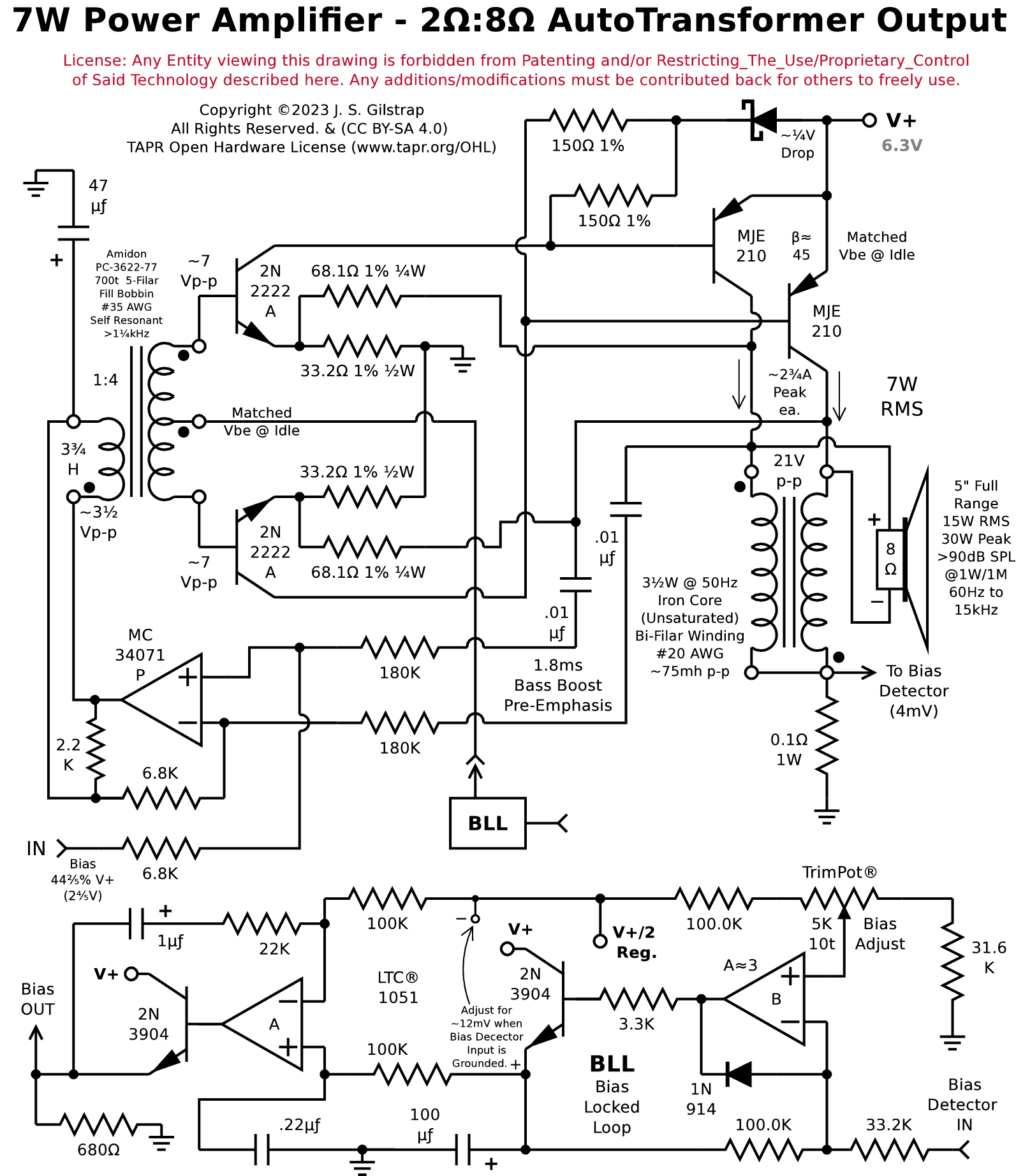
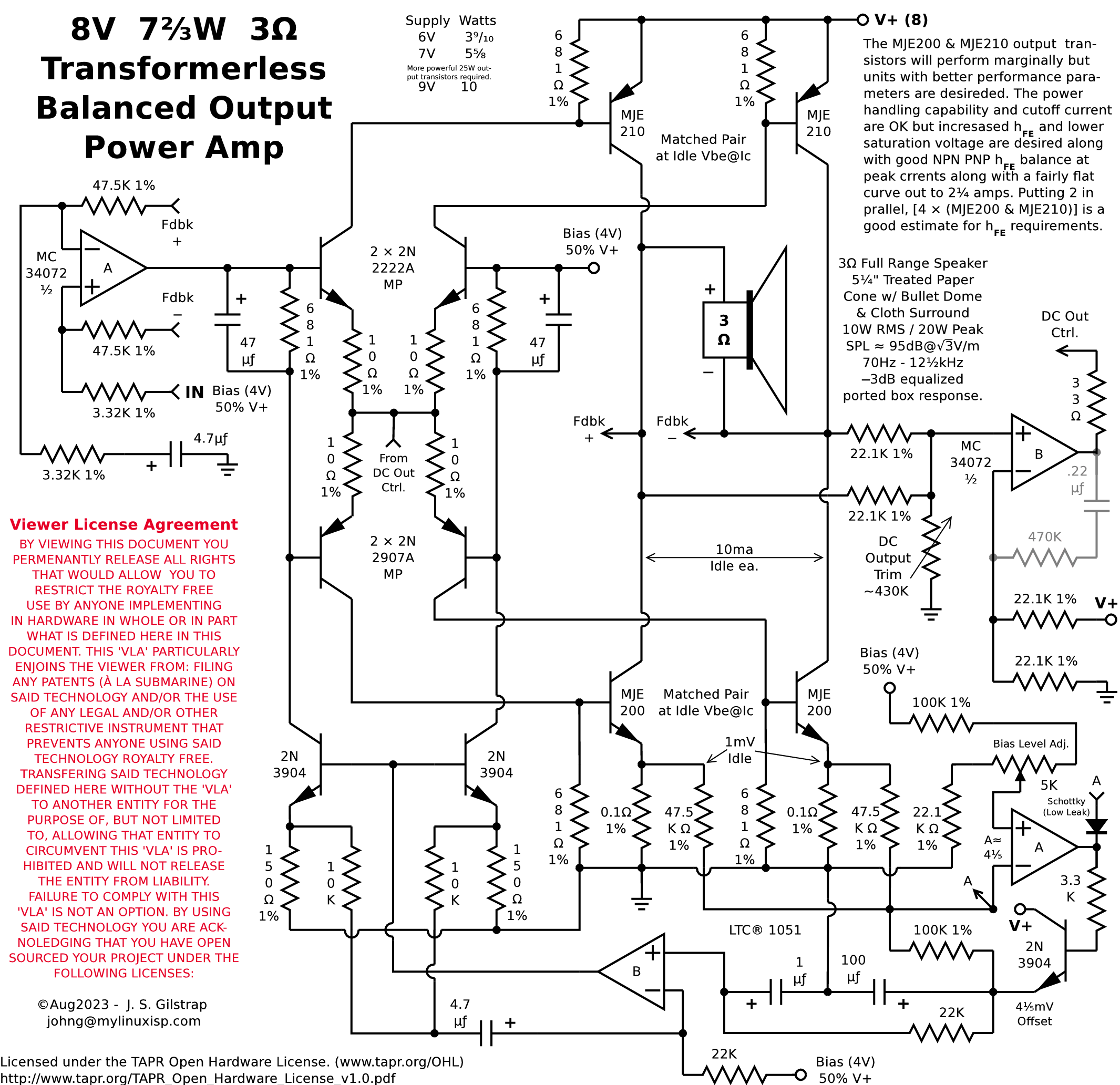
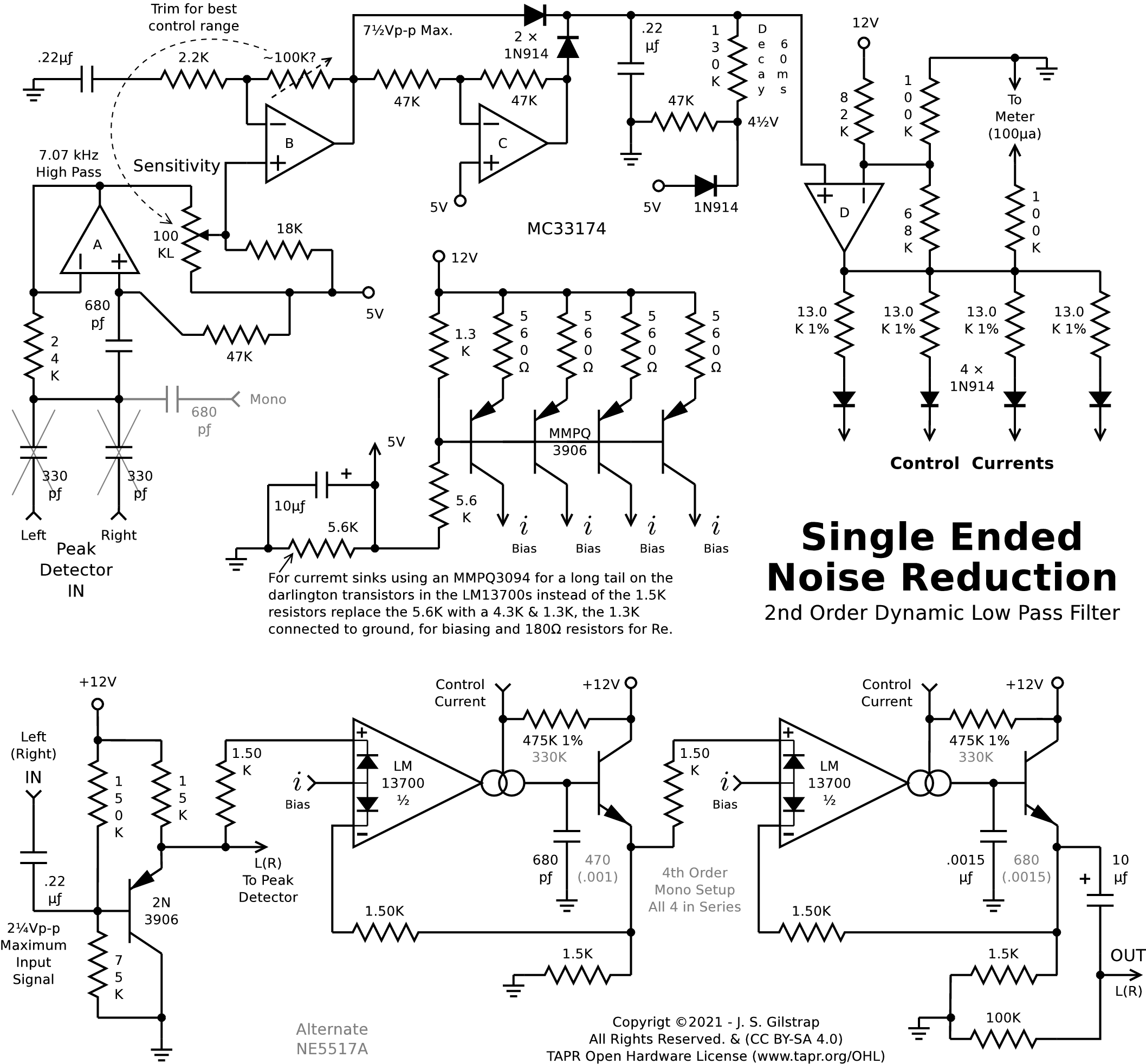
Audio Filters
Here are some audio filters, high pass, low pass, 2nd & 3rd order,
bandpass filters, notch filters, phono preamp with rumble filter, and mic
preamp.
Amidon
Jan 2001 Inductive Component Catalog with extensive graphs and information for
iron powder and ferrite cores.
3 Stage IF Filter and a Closup
This setup provides a smooth wide bandwidth response with a very flat passband,
better than some ceramic filters. Used with a RF bandpass of ±7½kHz, a 78½µs
de-emphasis with a pole at 5.565kHz, and a Chebyshev Low Pass Filter at 15⅓kHz
with a Q of 1¾ providing a boost of 4.85dB at 'f' will produce a -3dB response
at 12½kHz for transmitted signal with 75µs pre-emphasis with a 8.7kHz pole.
MC13028 Pocket Radio ─
Schematic for an AMAX spec. pocket sized radio with 11kHz audio bandwidth,
10kHz whistle filters, and post detection eq. for proper de-emphasis.
3.6MHz L-C replacements for those hard to find
ceramic resonators needed for Motorola chips.
MC13028 Decoder Board with wide ceramic
filter and post detection filtering: NRSC Eq, high Q 10KHz tunable notch filter,
and 2nd order low pass filter with a +12.2db boost at ~11.3KHz. Here is an
SMD version the size of a business card that just
contains the decoder and post detection filtering but not the 8V regulator, IF
input amps or IF filter. The post detection filtering is tuned for an IF using
a ±10KHz ceramic filter.
Extra Mono ─ Has your favorite AM Stereo music
station been assimilated by the "Evil Empire" and the station
management has been seduced by the "Dark Side" into turing off the
AM Stereo Exciter with there being no possibility of it ever being turned back
on? Well most likely they are still broadcasting out to the 10.2KHz NRSC limit
and you can still enjoy that wideband sound. This curcuit will give you that
wideband response and provides a 10KHz notch filter to eliminate the adjacent
carrier whistle. It is much simplier than an AM Stereo decoder to build and
could be assembled and installed in a short period of time.
Signal Pre-Processing for TX.
600ohm Balanced Input with Gain Adj., 5th Order 50Hz High Pass Filter, 3rd Order
170Hz High Pass L─R Filter, High Frequency Peak Smoother, 5th Order 10.2KHz Low
Pass Filter, Choice of Audio Compressor, and NRSC Pre-Emphasis.
Realistic TM-152 AMAX Upgrade
This circuit is to update the Realistic TM-152 to meet the AMAX frequency
response using a dual IF filter setup, 10KHz notch filters, NRSC 75us de-
emphasis, 6db buffer amp, tweaked up pilot tone circuitry and an optional
sychronous adapter. The only thing missing is a noise blanker.
Realistic TM-152 Harris Synchronous Detection Hack
This circuit is more complex than the one in the AMAX drawing to hack the
Motorola® MC13020 decoder chip for Harris synchronous detection. It provides
automatic switching when the PLL is locked and a center tuning indicator.
Harris Synchronous Detection Hack for DTR
This is a somewhat less complex circuit than the one for the TM-152 as it does
not provide a center tuning indicator because it is not necessary but does
provide automatic switching when the PLL is locked.
C-Quam Decoder
This is a schematic for a C-QuAM® adapter using the
Motorola® MC13020 decoder chip to convert a mono AM receiver to stereo. It
has a ±7½KHz IF ceramic filter, 10KHz notch filter, low pass chebychev
filter to boost frequencies above 7½KHz for a 3dB response at 9.KHz that also
provides of 6db overall gain, AGC with a PLL style loop filter for a constant
carrier level tracking, and a tweaked pilot tone and co-channel circuit to for
positive stereo detection even under marginal conditions. This has a flat
frequency response and does not have AMAX equilization.
What's all that buzzing about? No analog AM now, DX or local! Welocme to digital
hash thank's to Din of iNiquity's iBloc HD Radio = All Buzz, All the Time!
Courtesy of Google Translate:
(If there are mistakes you know what's to blame ;-)
Was ist all das geschwirr herum? Keine analogen MW/AM jetzt, DX oder lokale! Willkommen auf digitalis
Rauschen dank Lärm/Höhle von die iNiquity iBlockieren HD Radio = Alle Schwirren, die Ganze Zeit!
Qu'est-ce que tout ce qui bourdonnaient autour? Pas analogique MW/AM maintenant, DX ou locale! Beinvenue au bruit
numéique merci à Bourdonnement/Lieu de l'iNiquité iBloquer HD Radio = Tous les Bourdonnement, en Tout Temps!
O que é tudo o que zumbindo em volta de? Não analógico MW/AM agora, DX ou local! Bem-vindo ao ruído
digital graças a Ruído/Caverna de la iNiquidad iBloquear HD Rádio = Todos Zumbido, Todo o Tempo!
Atención México:
¿Qué es todo ese zumbido alrededor de? ¡No analógica MW/AM ahora, DX o local! Beinvinedo a ruidos
digitalis gracias a Estruendo/Cueva de iNiquidad iBloquear HD Radio = ¡Todos Zumbido, Todo el Tiempo!
Che è tutto quel ronzio intorno? No analogico MW/AM ora! DX o urbano. Beinventui al rumore
digitale grazie a Rumore/Tana di iNiquità del iBlocco HD Radio = Tutto Ronzio, Tutto il Tempo!
All these modifications are centered around the Motorola® MC13020
C-QuAM® AM-Stereo decoder chip. In the future I hope to have more
information on the newer Motorola® chips and maybe some of the japanese
chips if they are still available. I will try to add more technical articles,
schematics, and graphs in the future. Information may be revised from time to
time to improve and clarify for accuuacy purposes. I want all you
hobbyist and tinkerers to take full advantage of this information in the
promotion and enjoyment of AM Stereo. Download it and share it with your
freinds. If you have any questions or comments about this page and its links
contact me.
Use of The AM Stereo Tech Zone™ is restricted to
refering to this site. If anyone wants to use any of this
information in a national publication in printed or electronic form it must be
used with my permission so please contact me.


