Synchronous Detection
vs Envelope Detection

(A Synchronous Detector Converter for MC13020P)


This is manually operated in that it will NOT automatically switch from Envelope to Synchronous and back. You must flip the switch to the open position while tuning and flip it back after tuning. A more complex design that senses signal level at pin 4, PLL loop volts at pin 19 and the lock signal at pin 10 could automate the switching while tuning.

Here is an automatic version that offers a blend to QUAM fearure.


4-Way Synchronous Quadrature Modulation Decoder using the MC13020 Chip

A A Discrete QAM Synchronous Detector with Post Detection Eq.

A A Discrete QAM Synchronous Detector using a Quad Analog Switch.

Discrete QAM & ISB Document with circuits.
he following was started as a short description on synchronous detection but has turned into a rather long overview of some of the AM Stereo systems particually C-QUAM and Harris. It also has my take on the pros and cons of some of the various systems. Tending to follow a train of thought I may go off onto a sub-topic that is related to the current topic but try to return to it. I tend to repeat stuff from a slightly different prespective to introduce other details that are related to it.
Why
Synchronous Detection
Is Better


During good signal conditions and little or no interference there is really little audible difference between envelope and synchronous mode. Even when detecting C-QUAM stereo as QUAM your ear will tell a faint difference between the two but not as objectional as light to moderate interference would cause. During daytime listening there is little need to disabe the Cosθ corrector circuit and switch to synchronous QAM sacrificing distortion correction and slight loss in audible separation, but at night when interference is medium to high and/or skywave reception distorts the signal in such a way to cause signifigant distortion with the envelope detector this is where synchronous detection excels. One of Motorola's original patent 4,218,586 for C-QUAM describes that reasonable performance is expected when a C-QUAM signal is decoded with a regular QUAM receiver in the last paragraph.

n AM the carrier is equal to the amplitude of the sum of both of the sidebands during modulation and you could say that the carrier is the beat frequency to which the sidebands are detected with. Both sidebands beat against each other in such a way to null out any signal 90° out of phase of the carrier and reinforce the in phase signal with the carrier. It is important that there is reception of both sidebands with the same relative phase/delay and amplitude to recover a non distorted signal. If not, as when the receiver is mistuned and distortion is audible, the vectors of both upper and lower sidebands do not beat correctly against the carrier to to reproduce the original signal. Phase modulation is also present during asymetrical sideband reception of a mono signal. The higher the modulation level is in relation to the carrier the more pronounced this effect is. So for envelope reception it is important to have a matching pair of sidebands for each tone. When an interfering signal from an adjacent station interferes with the station you are trying to receive it only places signals on one side of the carrier and not the otner. That signal is not only received but it also produces harmonic distortion that is a non-linear function of both the desired signal and the interfering signal as a form of a quadrature type of distortion in that a signal only on one side of the carrier contains both in phase and quadrature information much the same way that QUAM does since the Q signal was generated from a carrier 90° out of phase with the in phase 1+L+R signal, hence the purpose for C-QUAM.

In short the envelope of an AM signal is fragile in transit to the receiver. For linear mono modulation it should contain only envelope modulation and no phase modulation. Interference that is not coherent to the carrier will alter the signal in both amplitude and phase and produce distortion because the representation of the envelope in rectangular co-ordinates is a non-linear function and any additional non-coherent information added to the signal will transfer to the envelope non-linearly. It is a multiplication/division process and not additive.

So you can see that when a signal interferes with another that not only do you hear both signals but you also get an appreciable amount of harmonic distortion also. Since the Cosθ signal is derived from both the Env and the I signal for C-QUAM decoding any harmonic distortion from the Env Det is modulated into both the I & Q synchronously detected signals. As interference increases the distortion does not increase linearly but somewhat exponentially. The real problen occurs when the original envelope modulation approaches -100% modulation and an interfering signal at that particular moment could be several times the magnitude resulting in phase angles for Cosθ that are nowhere close to the original signal. As θ approaches 90° and 1/Cosθ goes to infinity or when the I Det goes negative which causes the Cosθ negative feedback circuit to switch to positive feedback and latch up, large spikes are modulated into both I & Q signals creating very high distortion in L─R that is several times the strength of the interfering signal itself which is extremely objectionable.

C-QUAM not only requires the reception of each pair of sidebands to be received with the same relative phase/delay and amplitude but also the predistorted sidebands that are harmonics of the original signal generated by the Cosθ modulation of the original QUAM signal must also be received with the same phase/delay and amplitude as the fundamental of thoes harmonics to ensure proper distortion correction. IF filtering for C-QUAM requires that the Group Delay Time for the passband of the filter be as flat as possible to maximize distortion correction. This is also true for all of the non-linear systems like Kahn-ISB, Belar AM-FM and Magnavox AM-PM. These filters are called Gaussian filters and are not optimized for maximally flat amplitude response as a butterworth filter is but are tuned for a flat delay time. As a result their amplitude response is not as flat in the passband as a butterworth filter but produces a gradual roll off in the passband. Their response curve is more rounded as compared to a butterworth that has a very flat passband with a linear db/oct roll off.

In the MC13020P cosine correction is derived from the division of the Env signal by the I signal, (1+L+R)×Cosθ. Actualy it is generated by sending the two signals into the inputs of a differental amplifier and comparing the two. Any difference between the two is amplified many times and is sent to control a variable gain amp that amplitude modulates the signals going to the I & Q Det but not the Env Det. If the variable gain amp has a linear input response then the output of the differental amp is 1/Cosθ beacuse of the negative feedback loop. This method is very accurate for converting C-QUAM back to QUAM during good signal conditions but fails miserably when interference causes this circuit to behave irradically. The Env Det in this chip is probably the same kind of synchronous detector that is used for the I Det so output will be equal with the same input thus ensuring good accuracy during cosine correction. It is probably a 4 quadrant multiplier like the MC1496 and when used for the Env Det the IF signal is injected into both of signal and carrier inputs. The rules of a 4 quadrant multiplier are:

P × P = P
N × P = N
P × N = N
N × N = P
Where:
N = Negative
P = Positive


Since both of the inputs get the same signal for the Env Det then when the envelope is negative the signal output is positive essentially functioning as an absolute value detector. The I Det can output both positive or negative because the carrier input is driven by the PLL. The I Det can go negative and will be 180° out of phase of the PLL and P × N = N under those conditions. When this happens, the I output being negative in relation to the Env output, the cosine corrector circuit tries to increase the gain to increase the value of the I Det but increases it in a negative direction and thus positive feedback and latchup results. The newer Motorola decoder chips have addressed some of these problems by maybe shutting off Cosθ correction for L─R and also reducing L─R level (blending) appropiately during these kinds of conditions and other methods are probably used also but it still appears that they are using the same kind of Env Det for L+R. Their documentation does not say too much about what goes on inside the chip regarding this or if they are employing some kind of advanced detection scheme for the envelope. From their diagrams on the MC13022 it appears that L+R is taken right off the filter capacitor on pin 1 for the Env Det and is sent directly to the matrix to obtain both the Left & Right signals and on the MC13028 there appears no filter capacitors for the detectors for any of the three signals.

A synchronous detector also preforms this same function as the carrier and will also detect a signal that has its carrier suppressed as in SSB or DSB-AM without distortion. The L─R portion is also generated as a DSB-AM suppressed carrier before it is added with the 1+L+R modulated signal. To better understand the reason why a synchronous detector will detect a signal that doesn't have a carrier as in DSB or SSB, which also has no matching sideband, is that it effectivly reinserts a carrier for the sidebands to beat against. Since the amount of Env Det distortion during interference is defined by the strength of the sidebands in relation to the carrier the synchronous detector effectivly inserts a carrier many times the strength of the sidebands thus reducing the distortion to a minimum if not eliminating it all together. This has a great advantage over envelope detection for a couple of reasons. First, an interfering signal is received as a simple summation with the desired signal with little if any quadrature type distortion. Second, whichever signal captures the PLL and locks to it the PLL locked signal defines the carrier and all signals are detected in relation to it and not one or more of the carriers from adjacent or co-channel interference. With a PLL that has a capture window of ±2½kHz this prevents the carrier of an adjacent signal from capturing the PLL. For co-channel signals the effect is similar to the capture effect of FM when the capture range of the PLL is defined in db in relation to the strength of one carrier to another. Essentially the detection technique for L─R and FM or PM is the same when using a PLL because the L─R modulation is 90° out of phase of the carrier.

With synchronous detection the PLL is the sole beat frequency where all signals are detected in relation to it. One major benefit is that wider IF bandwidths can be used without the adverse effects associated with envelope detectors. Theroetically a ±15kHz could be used even under noisy conditions as long as the PLL maintains a good lock on the desired carrier which is something PLLs are good at. A ±12½kHz would be more practicle for most music type program material as anything above that would be rarely missed and would be unuseable even under light to moderate noise conditions. A 2nd or 3rd order variable low pass filter at the audio level that is user controlled could be used to adjust the bandwidth response that is normally controlled through IF filter selection. A dynamically controlled filter like the DNR chip LM1894 could also be used. Two or three could be cascaded together to give the effects of a variable IF bandpass filter that is dynamically controlled, something that would be difficult to accomplish at the IF level.
The envelope of the signal is an unreliable source for information during interference conditions for decoding because it represents both in phase and out of phase information in a non-linear manner where the harmonics are the product of both the desired signal and the interfering signal. Even if you obtained both the I & Q signals through synchronous detection and then obtained the envelope through the square root of the sum of the two squares whether it be analog or digital it would still produce the same harmonics that didn't exist in the two signals themselves, and it's the math that does it. Synchronous detection also provides some protection from impulse noise giving a somewhat more accurate representation of the envelope so some integrity of the signal is gained over plain envelope detection. Any time you have multiplying or dividing of two or more signals going on there is always going to be signals generated that weren't present in the two original signals or the reduction or elimination of signals that were present in the two original signals which what is going on when C-QUAM is properly decoded. Having a circuit that preforms multiplication and division that is not immune from interference where the interference becomes another factor in the decoding process only introduces distortion into a non distorted synchronously detected L─R. In fact the amount of distortion introduced into L─R can be greater than the distortion in the L+R envelope signal. The first multiplicative process is envelope detection itself because of the non-linear nature of the envelope detector's response to the desired and interfering signals. The second is cosine correction which uses a corrupted 1+L+R as a go by to model a synchronously detected 1+L+R by. I have to give credit to Motorola for finding a way to detect a phase modulated L─R that was free from AM noise characteristics during transmittion with all the shortcomings of an envelope detector and then some. The amount of error depends on the magnitude of the desired signal in relation to the magnitude interfering signal. During the modulation of the desired signal at +125% modulation peaks an interfering signal causes little error in decoding but during -100% modulation peaks, when the desired signal's envelope vanishes, an interfering signal, regardless of its magnitude, will cause a full 360° of rotation of the phase in relation to the PLL, which controls the I Det, will cause cosine correction to vary from a gain of one, when the interfering signal's phase is 0° in relation to the I detector, to infinite gain when the interfering signal's phase is approaching or greater than ±90° in relation to the I detector resulting in positive feedback and/or latch up within the cosine corrector circuit. There are tricks that can be done to force the variable gain amp to a gain ≤1 to minimize distortion during these negative modulation peaks. I'm sure that some kind of technique like this is used in the newer Motorola chips that have greatly improved detection but unless they blend the L+R envelope detection towards synchronous detection the MC13020 can still be adapted to produce superior detection for L+R during high levels of interference than some of the newer chips. The MC13022 has pins for I, Q & Env but there is no way to disable the error amp with a large capacitor. Now there is a signal quality detector that is supposed to reduce the amount of cosine correction and other stuff as interference increases so it may be possible to feed the I Det signal back into the Env Det pin when cosine correction is completely disabled if that ever occurs during poor signal conditions. The MC13028 and the MC13029 has no external connections for this so it would not be possible.
Linear QAM occupies the same bandwidth as mono AM so the excessive splatter of harmonics is not an issue as it is with the non-linear systems. The quadrature distortion for envelope detectors on program material is mostly even harmonics 2nd, 4th, 6th... and these harmonics are usually present in the program material anyway and tends to add brightness and usually does not appear as distortion to the listener. The argument that the envelope must equal L+R for mono compatibility is somewhat or a red herring. In order for an envelope detecter to receive a non-linear signal without distortion the IF filtering must have a relatively flat delay response, something that most of the older receivers and smaller radios don't have. This was the argument for the non-linear systems in the first place that the envelope must be equal to L+R. This has produced a poor tradeoff in order to maintain only patrial envelope compatibility. The transmitted frequency response is the first to be sacrificed to prevent excess splatter and the second is in reception. Not moving away from the envelope detector and reaping the benefits of synchronous detectors is too big a sacrifice to maintain only partial compatibility with envelope detectors. Some types of distrotion might be even greater under certain circumstances with the various types IF filters. The information in the following table was obtained from a graph in the Dec '78 issue of PE.

Mono Envelope Detector Distortion for IF filters

SystemNoneEllipticButterworth*Synchronous
Belar0%16.8%9.8%4.0%
Magnavox0%19.9%11.7%4.4%
Motorola0%18.1%11.7%3.4%
Kahn0%15.2%9.4%3.2%
Harris0%3.3%2.2%0.9%
* Synchronously Tuned - I assume that this refers
to a filter that has a flat Group Delay Response.

Of all the non-linear systems the Kahn Independent Side Band system has the least distortion of all for the various filters. Leonard Kahn has probably had the most experience in AM Stereo as he is one of the earlir pioneers in the field. The Kahn system has been refined over the years and has seemed to have produced a well balanced system. Independent Side Band has some definite advantages over all the others under certain kinds of adverse reception. There is no platform motion that is sometimes experienced during skywave reception. Interference on one side of the carrier only appears in one of the channels. The system could also be used to detect a mono signal where there is heavy interference on one side of the carrier and not the other. The Harris system has the least distortion of all of them. This version of Harris used the variable phase angle by processing L─R with a compressor and modulating the L─R carrier at a reduced level limiting the phase deviation to a maximum of ±15° to maintain envelope compatibility.
The rest of this is mostly about C-QUAM and audio filtering.

With the phase modulation of a QAM signal phase increases on dips of 1+L+R modulation along with the amplitude of the L─R modulation to produce a non-linear type of phase modulation if detected with a ratio detector. Although the phase modulation is non-linear there are no multiple sidebands that are generated such as harmonics in relation to the fundamental modulating frequencies. The phase modulation is defined by Tan⁻¹[(L─R)/(1+L+R)]. The QUAM signal is a simple summation of two AM signals 1+L+R and L─R that are 90° apart and no multiplicative action takes place. The multiplicative action occurs with C-QUAM when the envelope is remodulated with 1+L+R and the phase protion of the QUAM signal does not have a proper envelope i.e. √(1+L+R)²+(L─R)². With this process harmonics that are up to six times the fundamental modulating signals are produced on both sides of the carrier.

C-QUAM is just an adaptation of Armstrong Phase Modulation and can you say 'prior art'. Armstrong gererated PM by using an unmodulated in phase carrier at 0° and the signal modulated a suppressed carrier at 90° just like L─R without any L+R modulation. The envelope is defined as √1²+M² where '1' is the in phase carrier at 0° and 'M' is the modulating signal at 90°. For any type of angular modulation the signal is limited to remove any amplitude modulation. Since there is no signal in the in phase channel the limiting to remove any envelope modulation effectively multiplies amplitude of the signal by the Cosine of the angular modulation. The FCC defines one of the phase deviation limits for C-QUAM as pure Armstrong PM. It states:

§ 73.128 (6) A peak phase modulation of ±0.785 radians (±45°) under the condition of the difference (L─R) channel modulation and the absence of envelope (L+R) modulation and pilot signal shall represent 100% modulation of the difference channel.

A C-QUAM AM-Stereo exciter can be used to generate an Armstrong phase modulated signal. Send 'M' to the Left input and '─M' to the Right input. The Left and Right inputs are 180° out of phase so they cancel each other out in the L+R channel but reinforce each other in the L─R channel. To decode it you could use a C-QUAM decoder chip and all distortion would be removed. You would even have a balanced output from the chip, Left would be +Out and Right would be -Out. A 25Hz pilot tone would need to be there to trigger the chip into stereo mode also. You could say that Armstrong was C-QUAMing years ago, many years ago.

With the older Analog C-QUAM exciters excessive spectra could be a problem if proper filtering is not used to suppress these extra sidebands that are outside of the audible range. One method would be to generate the C-QUAM signal at an IF frequency, filter it through a ceramic type Gaussian filter and then hetrodyne it up to the desired transmitted frequency. A six element ±12½kHz ceramic filter would probably do a good job of suppressing the unwanted sidebands. This method has some drawbacks though. The most accurate method of signal generation with the least amount of noise would be to generate the QUAM signal at the desired transmitting frequency limit it and send that to the RF modulator in place of the carrier oscillator. The AM portion of the signal is 1+L+R and is used to modulate the envelope portion of the signal. Using the IF method more processing stages will introduce more noise, distortion and loss of separation so an alternative method is needed. Reducing the frequency response of L─R to a point when using RF generation that is acceptable to the FCC bandwidth restrictions would also work. For C-QUAM audio bandwidth for L─R would have to be approximately half that of L+R. An L+R with a response of 15kHz would only allow 7½kHz of L─R so as to fit into the FCC allocated bandwidth. Now with the new regulations associated with AMAX which specifies a 75us pre-emphasis and a frequency cutoff of 10.2kHz L─R would have to be reduced to 5.1kHz if no post filtering is used.

Now enter the age of DSP where things can easily be done in the digital world where in analog it would be difficult to impossible. The pre-emphasis and frequency response can be digitally processed for the AMAX specifications and have a completely flat response out to 10.2kHz and a complete cutoff above 10.2kHz. The C-QUAMed signal could also be processed this way to eliminate the extra harmonics above 10.2kHz generated from multiplying the signal by the Cosine of the angular modulation. A complete sharp cut off has some drawbacks though. It will cause excessive audio ringing of the high frequencies so a more gradual roll off should be used instead of a vertical cut off to reduce this.
One of the major problems when a wide IF filter is used with envelope detection is the carrier of an adjacent signal can be strong enough to act as the beat frequency and override the desired carrier. For filters that are ±10kHz or wider an adjacent signal whos carrier is only a quarter the amplitude of the desired carrier is equal to the strength of the desired sideband that is a 100% modulation of a single tone. This is why 10kHz whistle filters are necessary because an adjacent carrier can produce a very strong and obnoxious whistle. The only way to reduce this problen is to use a narrower IF filter. A ±7½kHz 6 element ceramic filter such as the muRata SFH450E makes a good choice to suppress the adjacent carrier to the level of the sidebands of the adjacent signal. If the sidebands of the adjacent signal are strong enough to cause a signifigant amount of interference then switching to a narrower filter does do some to reduce distortion but there are unwanted sidebands at signifigent levels present even within the bandwidth of a ±4½kHz filter. For a ±7½kHz filter post detection equilization can be used to boost signals above 7½kHz to have an essentially flat response out to 9kHz.

Here is a low pass Chebychev filter that can be used to boost the signals above 7½kHz for use with a ±7½kHz ceramic filter. It also compensates for a single RF stage with a bandwidth of 20kHz, a single IF LC stage with a bandwidth of 30kHz, and a detector filter of fc@13⅖kHz to give a very flat response. The overall response is:

0-1kHz5kHz7½kHz9kHz10kHz12.5kHz
0db+.38db-.25db3db-8.5db-23.6db

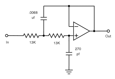
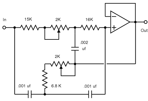
fc=1/(2πR√C1×C2)
Q=√C1/2√C2
fc=9.035kHz
Q=2.51
A=1
Gain@fc=+8db


Drawbacks to this approach is that some loss in signal to noise ratio in the top end compared to using a wider IF filter. This is usually not a problem since the reception of background noise is usually much greater. The sharp roll off will produce audio ringing that is more pronounced on certain program material than others. The phase and delay difference of the higher upper and lower sidebands caused by the asymetry of the Ceramic filter, antenna and IF LC filters affects stereo separation and distortion correction. The distortion isn't much of an issue since the second harmonics probably start well above 15kHz and this filter and the detector filter will have at least an attenuation of ─6db @ 15kHz and ─12db @ 20kHz.
For the 10kHz whistle here is a very sharp and deep notch filter with a Q=~50.

The new AMAX standard requires a 75us de-emphasis with a 8.7kHz shelf.

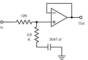
12K+3.9K=15.9K
15.9K×.0047µƒ=74.7µs
1/(2π×74.7µs)=2.13kHz
1/(2π×3.9K×.0047µƒ)=8.683Hz
Close enough.


You can subsitute the Op-Amps in the above three figures with a NPN or a PNP Darlington Transistor with an emitter resistor or current source to ground or V+ whether you use a NPN or PNP respectively for a source follower.

Capacitors for all 3 circuits should be temperature stable high Q and low ESR.
Copyright ©2001 ©2018 - J. S. Gilstrap

This document may be shared with anyone provided that the copyright notice stays with it. In fair use, quoting from this article for published documentation I require that my name referenced. Publishing in full in printed media will fall under different terms and must have my permission. Reference not required for casual quoting in internet discussion groups but would be appreciated. All trademarks i.e Belar, Magnavox, Motorola, C-QUAM, Kahn, Harris, Popular Electronics and others are property of their respective owners.